Design of Transmission Shafts for Deep Water Well Mud Extractor
Objective:
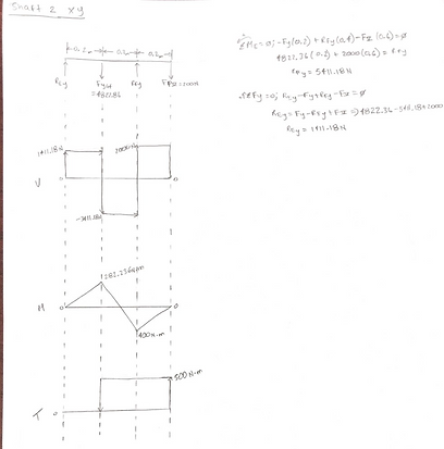
Design three transmission shafts to lift a 2kN load 80 meters within 90 seconds. The motor must input enough power into shaft 1 so that the load can be lifted along with the generator (on shaft 3) being powered at 1.5 kW. Based on the forces that act upon the transmission shafts, a safe diameter for S1, S2, and S3 must be attained.

Introduction:
The purpose of this project is to design three transmission shafts that will power a deep water well mud extractor. The engineers would have to know the weight of the load being lifted, as well as power input required by each motor to be able to safely escort the load to its designated location. The critical specification in this project is the diameter of the transmission shafts as they are critical in allowing the mud extractor the ability to lift its load with precision and safety. Given certain specifications about the project is a start, however the engineers will have to combine their knowledge of mechanics of materials, machine design, and physics to be able to compute the necessary component specifications. The engineers had to select some factors of their own: the stress yield point was chosen as 350 MPA, the material was chosen as steel, the factor of safety was 2, the shock under bending factor was 1, the shock under torsion factor was 1, the endurance limit was selected as 124 MPA, and the max shear stress was selected as 175 MPA.


The following conditions are given;
1. A 2 kN load due to mud should be lifted 80 meters within 90 seconds.
2. Power is input through the motor attached to shaft S1.
3. The extra power spins a 1.5 kW generator by shaft S3.
4. The tension ratio for pulley III is 8:1. Also, assume angle of wrap of the belts on the pulleys is 180o.
Hand Calculations:


